




Point Cloud to Steel Model: How Scan-to-BIM Is Changing Renovation Detailing
Point Cloud to Steel Model: How Scan-to-BIM Is Changing Renovation Detailing
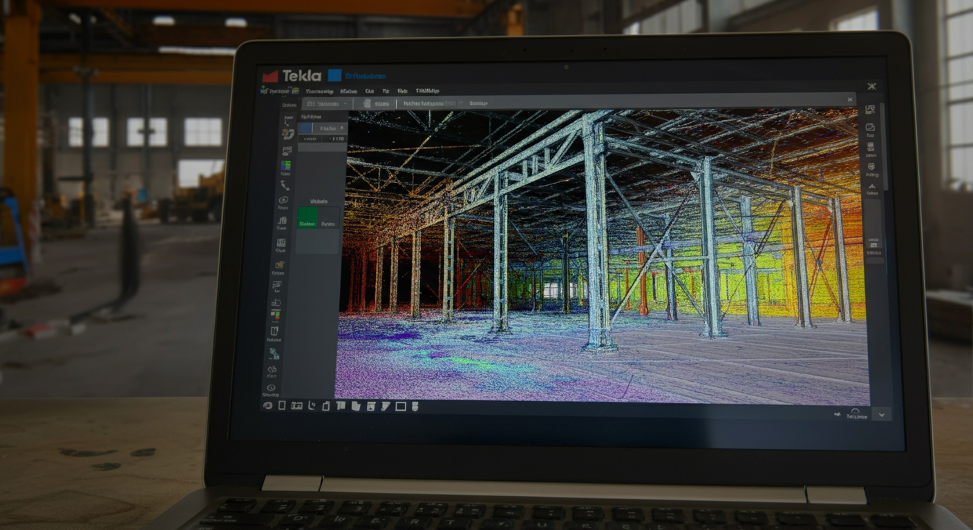
Renovation projects fail at the connection. Specifically at the interface between the new work and whatever was actually built fifteen or forty years ago, which may or may not resemble the drawings in the archive. Old steel structures drift. Columns move. Embeds land where the concrete crew put them, not where the drawings said to. When you're connecting new structure to existing, those discrepancies show up as field fits that don't work and connections that need to be cut and re-detailed under schedule pressure. Point cloud scanning addresses this directly. A lidar scan of an existing structure gives you a millimeter-accurate picture of where everything actually is, not where the original drawings thought it was. This post covers how scan-to-BIM works in a steel detailing context, what the workflow looks like from scan collection through model delivery, and where the technology genuinely earns its cost on renovation and addition projects.
The As-Built Lie Problem
Every renovation project starts with a set of drawings that are at least partially wrong. This isn't a criticism of the original design team — it's a structural reality. Steel gets fabricated to tolerances, erected to different tolerances, and then the building moves for decades. Concrete shrinks. Foundations settle unevenly. Prior renovations introduce undocumented modifications. By the time someone hands you a PDF of the 1987 structural drawings and says "connect to this," those drawings describe an idealized version of a building that may no longer exist.
The traditional mitigation is field verification: a detailer or fabricator rep visits the site, takes manual measurements with a tape and a plumb bob, and notes the deviations. That works for simple conditions. It breaks down when you're dealing with dozens of existing connection points spread across multiple floors, complex geometric conditions, or interfaces that are partially obscured by existing finishes and equipment. Manual field verify is slow, incomplete by nature, and subject to transcription error. Scan-to-BIM replaces that process with captured geometry — actual, dense, measurable data about where the steel is.
What a Point Cloud Actually Is
A point cloud is a three-dimensional dataset of discrete coordinate points captured by a lidar scanner. The scanner emits laser pulses, measures the return time, and builds a spatial map of every surface the beam contacts. A terrestrial scanner set up on a tripod will capture tens of millions of points per scan position, typically at accuracies in the 2–6mm range at relevant distances. A mobile scanning system — carried through a space rather than set up at fixed positions — trades some accuracy for speed of capture, which is useful for long corridors or large floor plates where setting up dozens of tripod positions isn't practical.
What you receive as a file is usually a `.RCP` (Autodesk ReCap project) or `.E57` format point cloud, sometimes delivered with individual `.RCS` scan files inside the project container. The raw data is dense: a thorough scan of a single floor of an industrial building can run several gigabytes before any processing. Before the cloud is usable, the individual scan positions need to be registered — aligned into a single unified coordinate system using common targets or automatic cloud-to-cloud matching.
Software for Working With Point Clouds in a Steel Context
The primary tools in a steel detailing workflow are:
Tekla Structures handles point cloud import natively. You can load a registered `.RCP` file directly into the model environment, set it to a real-world coordinate system, and then build or verify model geometry against the visible cloud. Tekla renders the cloud in the 3D view, letting you snap reference geometry and visually confirm that modeled members align with scanned surfaces.
Autodesk ReCap Pro is the standard preprocessing tool. Scan data from most major scanner brands — Leica, FARO, Trimble — imports into ReCap for registration, cleanup, and export into formats the modeling software can consume.
CloudCompare is open-source and handles deviation analysis — comparing two point clouds or a cloud against a mesh to produce colorized deviation maps. Useful for documenting how far existing conditions drift from the original drawing geometry.
Revit is common on the architectural side of adaptive reuse projects. Point cloud workflows in Revit are mature, but the structural detail work ultimately needs to happen in a fabrication-level tool like Tekla or SDS/2, not in a design-intent BIM environment.
What a Point Cloud Can and Can't Tell You
Point cloud data captures surfaces. This matters for steel detailing because it has implications for what you can and can't verify from scan data alone.
What you can verify with confidence: Column centerline locations, beam elevations, base plate positions, embed plate face locations, existing member profiles (by comparing cross-section geometry to database shapes), floor-to-floor heights, and clearance conditions around proposed new work.
Where scan data has limitations: Interior member dimensions behind fireproofing or cladding. Connection bolt patterns on surfaces facing away from the scanner — occlusion is real, and a W-shape flange facing a wall may not get captured cleanly. Weld conditions. Any geometry hidden behind MEP systems, equipment, or finishes that the scanner couldn't penetrate.
Scan resolution also matters. A coarse scan run quickly to hit a budget will miss small embeds and may not resolve thin gusset plates. If the scanning subcontractor doesn't understand what a structural detailer needs to work from, the data you receive may be geometrically complete at a macro level but insufficiently dense at the connection interfaces where the work actually happens.
The Workflow: Scan Through Model Delivery
In practice, the scan-to-BIM workflow for a steel renovation project runs as follows:
1. Scan collection. Scanning sub sets up scan positions throughout the project area, capturing the existing structure from multiple angles to minimize occlusion. Targets are placed for registration.
2. Registration. Individual scan positions are aligned into a unified project coordinate system in ReCap or the scanner's native software. The registered cloud is exported to `.RCP`.
3. Import into Tekla. The detailer loads the registered cloud into the Tekla model. Coordinate alignment to the structural grid is confirmed.
4. Model-against-scan. New structural members are modeled in Tekla in their design-intent locations. Existing steel — columns, beams, embeds — is either modeled from the scan geometry or verified against existing drawing dimensions using the cloud as a check.
5. Deviation reporting. Where existing conditions deviate from the original drawings beyond acceptable tolerances, the detailer documents the deviation and flags it to the EOR. Connection details for new-to-existing interfaces are developed based on actual scanned geometry, not assumed drawing geometry.
6. Model delivery. IFC or native Tekla files go to the fabricator with deviation documentation included. Connection plates, embed extensions, and field-fit allowances are detailed to actual conditions.
Where Scan-to-BIM Earns Its Cost
The scan subcontractor fee is real, but it's a fraction of the cost of one bad field fit on a crane pick. The return on investment concentrates in a few specific condition types:
Column base conditions. Existing anchor bolt patterns, base plate elevations, and grout conditions frequently drift from drawing. New column additions or moment frame connections to existing bases need actual anchor locations, not assumed ones.
Embed plate locations. Concrete crews set embeds. They don't always land exactly where the drawing said. On a multi-story renovation with dozens of embed-to-steel connections, scan data turns a potential RFI flood into a controlled modeling exercise.
Existing member profile verification. W-shapes from the 1970s and 1980s were rolled to different section databases. A W8x31 from 1982 may have slightly different flange geometry than the current AISC section. Scan cross-section comparison catches this before it affects connection plate detailing.
Clearance confirmation. Addition projects where new steel threads through existing occupied space need to verify clearance against actual conditions, not drawing conditions. Mechanical runs, existing columns, and architectural elements all show up in the cloud.
Common Failure Modes That Scan Data Prevents
Without scan data on a renovation project, the typical failure sequence goes: detail to drawing, fabricate, deliver to site, discover field condition doesn't match, issue field RFI, wait for EOR response, cut and re-detail connection in the field or return material to shop. Each cycle costs time and money. The specific failure modes scan data most reliably prevents are mislocated embed connections, wrong-elevation beam-to-column interfaces, and clearance conflicts that force field cuts to erected members.
What to Ask Before Starting a Renovation Project
If you're a fabricator or GC bringing scan-to-BIM into a renovation project, ask these questions early:
- Who is responsible for scanning, and what resolution is specified? "Scan the building" is not a scope. The scan specification should call out required accuracy, coverage of connection interfaces, and deliverable format.
- Has the scanning sub coordinated with the detailer? The people capturing the data need to know what the people consuming it require.
- What's the coordinate system? Scan data and structural model need to share a common coordinate reference. This gets sorted in pre-construction, not during detailing.
- What's the deviation tolerance protocol? Before the scan happens, the EOR and detailer should agree on what deviation magnitude triggers a formal RFI versus what gets absorbed in detailing.
NRSteel works on renovation and addition projects where existing conditions are the starting point, not an afterthought. If you're a fabricator working on a retrofit or adaptive reuse job and you've been handed a point cloud — or you need to get one — we can walk through the scan-to-BIM workflow and detail the existing-to-new interfaces from actual geometry. Get in touch to discuss your project scope.