




IFC Export from Tekla: What Your GC Is Actually Asking For
IFC Export from Tekla: What Your GC Is Actually Asking For
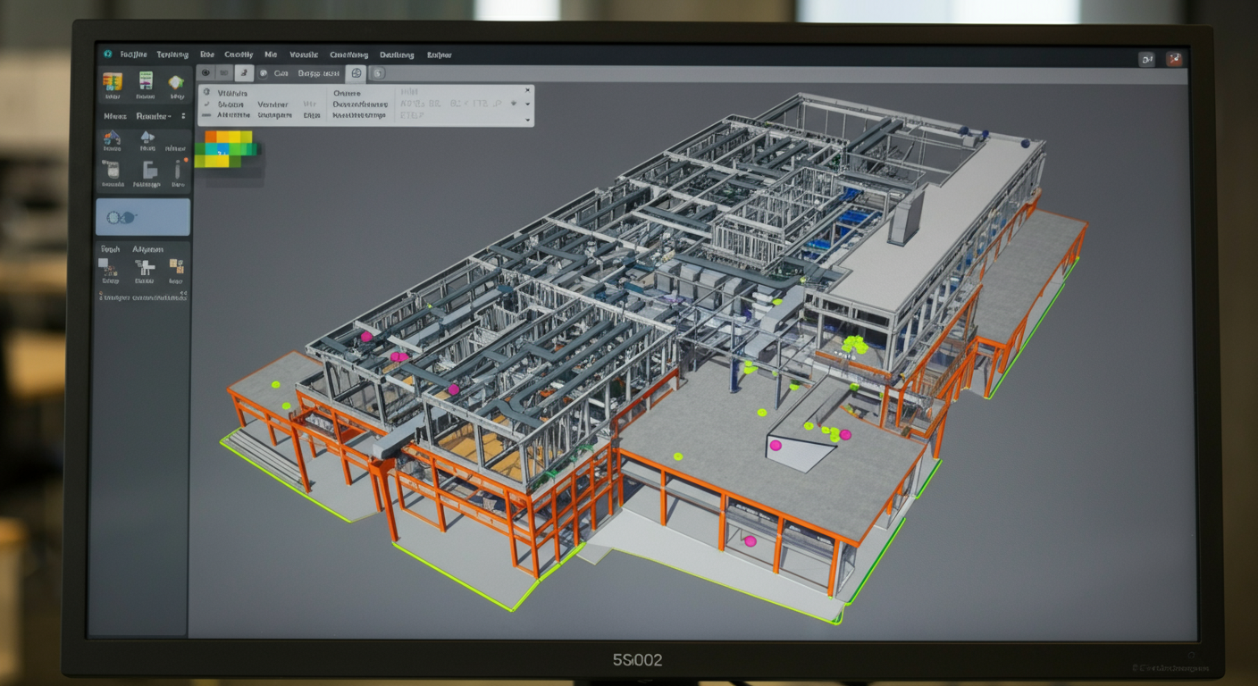
Your GC emails you on Tuesday: "We need an IFC from the steel model for coordination." If your detailer knows what they're doing, this is a 20-minute task. If they don't, it's a week of back-and-forth, three bad exports, and a coordination meeting where your model doesn't line up with the concrete. IFC — Industry Foundation Classes — is the open-format exchange standard that BIM coordination runs on, and it's increasingly non-negotiable on commercial and industrial projects over a certain size. The problem is that "send us an IFC" from a GC's project engineer often comes without any specification of what they actually need: which version, which property sets, which coordinate origin, which phase. This post covers what the IFC export process looks like inside Tekla Structures, what the common failure modes are, and how to make sure the file you send is actually usable on the other end — not just technically valid.
IFC Is a Data Format, Not a Button
The first misconception worth clearing up: IFC is not a model view. It's not a NWC, it's not a DWG, and it's not a PDF. IFC — Industry Foundation Classes — is an open, schema-based format maintained by buildingSMART International. It encodes geometry, object classification, material properties, and user-defined property sets into a single file that any IFC-compliant viewer or coordination platform can read without proprietary software.
When a GC's VDC coordinator asks for a steel IFC, they're asking for a file that they can federate with the structural concrete model, the mechanical model, the plumbing model — and run automated clash detection across all of them in Navisworks, BIM 360, or Revizto. What they are not asking for is a pretty screenshot or a lightweight viewer link. They need structured data with correct geometry and a coordinate system that matches every other model on the project.
That distinction matters because an IFC that opens without errors can still be completely useless for coordination if the property sets are wrong, the phase isn't filtered, or the origin is off by 500 feet.
What the GC Says vs. What the VDC Coordinator Actually Needs
Project engineers and VDC coordinators often speak different dialects of the same request. "Send an IFC" from the project engineer is usually a relay of a more specific requirement from whoever is running the BIM coordination model — and that person has a checklist.
What the VDC coordinator actually needs:
- A specific IFC schema version (usually IFC2x3 for Navisworks compatibility, sometimes IFC4 for newer platforms)
- A defined project base point and shared coordinate origin that matches the survey point in the concrete or civil model
- Object classification — IfcBeam, IfcColumn, IfcMember, IfcPlate — populated correctly so automated rules can identify steel elements
- Property sets with member marks, material grades, phases, and potentially erection sequence data
- Phase or filter scope — structural steel only, or does the GC also want miscellaneous steel, embeds, and deck?
If you ask the GC's project engineer these five questions and they can't answer them, escalate to the VDC coordinator directly. Getting this information upfront is the difference between one export and four.
IFC2x3 vs. IFC4: Which Version and Why It Matters
Tekla Structures exports both IFC2x3 and IFC4. IFC2x3 has been the dominant schema for over a decade and remains the standard for Navisworks workflows, which is what most GC coordination teams are still running. IFC4 introduced improved geometry representation, better property set handling, and more granular object typing — but platform support is still inconsistent.
The practical answer: default to IFC2x3 unless the GC's VDC coordinator explicitly requests IFC4. Navisworks Manage handles IFC2x3 well. IFC4 imports into Navisworks can produce geometry artifacts, stripped properties, or silent import failures that don't error out — they just show you wrong data.
If the project is running on a platform like Trimble Connect or Autodesk Construction Cloud with a modern coordination workflow, ask specifically which schema they're expecting. Don't assume.
Export Settings That Actually Matter in Tekla
Inside Tekla's IFC export dialog, there are settings that are cosmetic and settings that determine whether the file is usable. Focus on the following:
Object classification: Make sure IfcBeam, IfcColumn, IfcMember, and IfcPlate are mapped correctly to your Tekla object types. The default mapping is usually close but verify it — misclassified objects break automated clash rules on the receiving end.
Property sets: Tekla allows you to define custom property set export templates. At minimum, export member marks, profile names, material grades, and phase. If the GC is running a 4D simulation, erection sequence data should be included. Build a standard template and reuse it across projects.
Phase and filter scope: Use Tekla's export filter to limit what goes into the IFC. The coordination model should contain what the GC needs to check clearances and clashes — not your entire model including poured-in-place embeds, temporary bracing, and construction aids. Filter intentionally.
Reference point: Set this to your project base point, not the default model origin. This is where most IFC exports break down on federated models.
The Single Biggest Failure Mode: Coordinate Misalignment
If there is one thing that causes more wasted coordination meetings than anything else in a BIM workflow, it's misaligned coordinate systems. A steel IFC sitting 300 feet east of the concrete model is useless — and it happens constantly because detailers export from Tekla's internal model origin without checking what shared coordinate system the project is using.
Before you export anything, get the project base point from the GC's BIM coordinator. This is usually expressed as a survey coordinate (Northing/Easting/Elevation) and a project north rotation. In Tekla, set your model's project base point to match. Then export with the reference point set to that base point.
After export, open the IFC in a viewer — even the free Solibri Anywhere or IFC.js-based tools — and visually confirm orientation and location before sending. If the building footprint looks right and north is pointing where you'd expect, you're probably aligned. If it's rotated 27 degrees or sitting at the coordinate origin, you have a problem.
The GC's VDC coordinator cannot fix a coordinate mismatch on their end without significant manual work. That's your responsibility to catch before delivery.
Validating the Export Before You Send It
A technically valid IFC is not the same as a useful IFC. Before sending anything to the GC, run a quick self-review:
1. Open in a neutral viewer. Solibri Anywhere, usBIM.viewer, or the Tekla BIMsight viewer. Confirm geometry, orientation, and that member classification looks correct.
2. Check property sets. Select a few members and confirm that marks, profiles, and materials are populated. Empty property sets are a common export configuration mistake.
3. Run a rough self-clash. If you have Navisworks, append your IFC against the concrete model if available, or at minimum against itself. A self-clash check will surface geometry issues.
4. File size sanity check. An IFC for a 50,000 SF steel frame should be somewhere in the range of 20–150 MB depending on detail level. A 2 MB file probably has missing geometry. A 1.5 GB file probably has export settings that are too granular.
Ten minutes of self-review before delivery prevents a week of back-and-forth.
What You're Responsible For — and What Isn't Your Problem
A clear scope boundary matters here. As the steel detailer, your responsibility in a BIM coordination workflow is:
- Accurate geometry representing the fabricated steel assembly
- Correct object classification and populated property sets
- A coordinate system that matches the project base point
- Phase filtering as agreed with the GC's VDC coordinator
You are not responsible for clash resolution across trades, model management on the GC's coordination platform, or maintaining a live-updating federated model throughout design. If the mechanical contractor's ducts are running through your W18x35, that's a coordination finding — not a steel detailing error. RFIs from clash detection go back to the EOR and the affected trades. Your job is to give the coordination team a clean, accurate, complete steel IFC. What they do with it is theirs.
That distinction needs to be in your contract language if you're getting into regular BIM coordination workflows. Scope creep on model maintenance is real.
How NRSteel Handles IFC Coordination Requests
IFC export from Tekla Structures is part of standard project scope at NRSteel — not an add-on or a specialty service. Our Tekla models are built with BIM coordination in mind: property sets configured, phase filters in place, project base points set at project start rather than retrofitted before a deadline.
When a GC's VDC coordinator reaches out mid-project with a coordination request, we can turn around a validated IFC export same-day in most cases. We communicate directly with the VDC coordinator — not through relay chains — and we can join the coordination meeting when clash resolution requires steel-side clarification. That's the advantage of a team in the same time zone that actually understands what they exported.
If you're a fabricator being pressed into a BIM coordination workflow on a project and your current detailing partner is unclear on IFC export, that's worth a conversation before the coordination kickoff meeting.
NRSteel works exclusively with fabricators on commercial and institutional structural projects across the Southeast and nationwide. Get in touch to discuss your next job.